 Overview
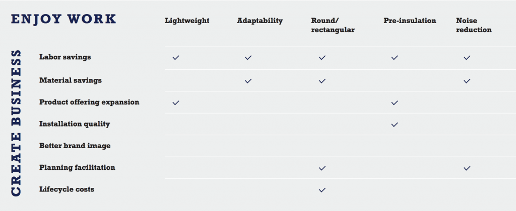
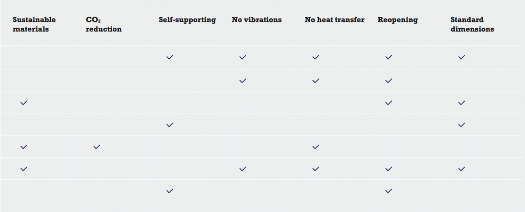
The CR Duct System offers a complete, pre-insulated system for heating, ventilation and air-conditioning.
CR Ducts and CR Bends consist mainly of glass, sand, and soda. CR Ducts and CR Bends both possess patented aluminum CR Foil on inner and outer surfaces, which provides a condensation barrier. The CR Duct System is built to the standard dimensions of the European ventilation market.
CR Ducts are standardly mounted round but, through use of the CR Transformer, can be made rectangular when necessary.
Applications
The CR Duct System can only be used for indoor installations.
CR products are not to be used for kitchen exhaust.
Local rules and regulations are to be recognized when installing any CR products. When calculating pressure drops, please use tables and diagrams for corresponding sheet metal products. CR products will be slightly lower.
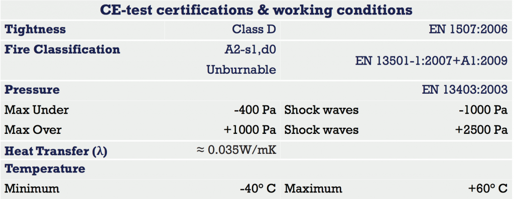
Certifications
The CR Duct System has been certified through SP Certification, the Swedish governing body for CE certification and accreditation. The matrix above represents tests and certifications that have been passed and awarded by SP Certification.
CR Duct
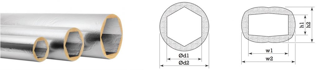
 CR Ducts are made of compressed glass wool with inner & outer surfaces covered by a layer of CR Foil.
All CR Ducts are shipped 235 cm long.
Average insulation thickness ≈ 30mm.
Water vapor resistance > 140m2 h Pa/mg
CR Bend 45°
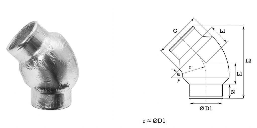
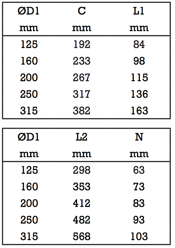 CR Bends are made of compressed glass wool with inner & outer surfaces covered by a layer of CR Foil.
Average insulation thickness ≈ 30mm.
Standard circular sheet metal nipples fit inside neck of CR Bends.
Water vapor resistance > 140m2 h Pa/mg
CR Bend 90°
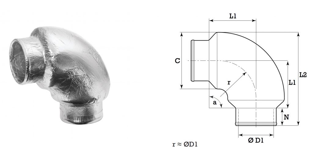
 CR Bends are made of compressed glass wool with inner & outer surfaces covered by a layer of CR Foil.
Average insulation thickness ≈ 30mm.
Standard circular sheet metal nipples fit inside neck of CR Bends.
Water vapor resistance > 140m2 h Pa/mg
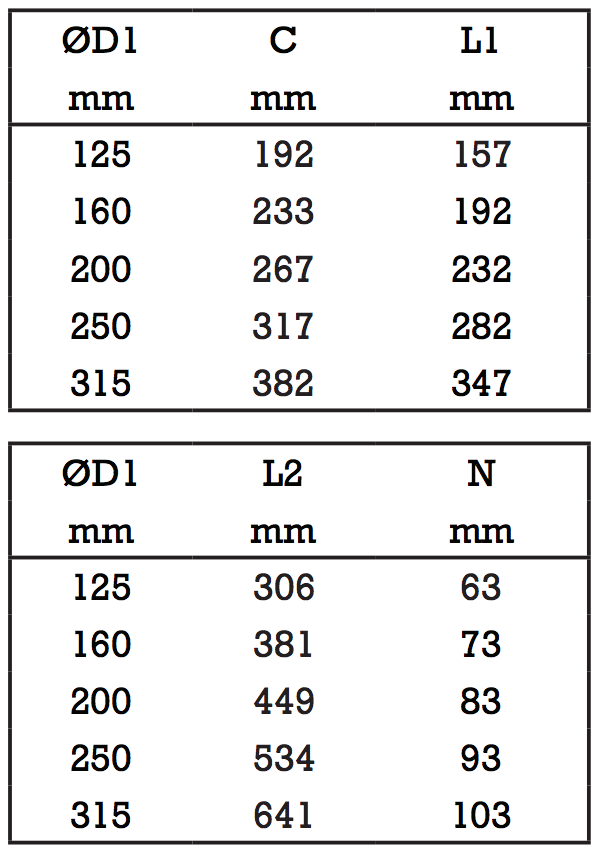
CR T-piece
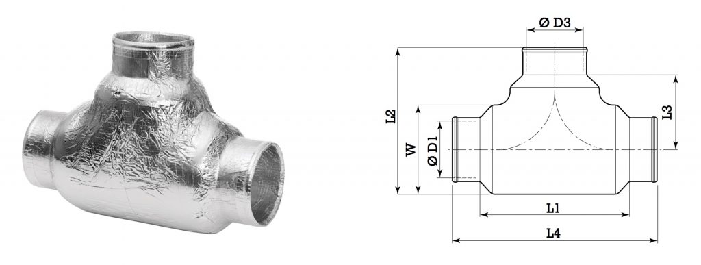
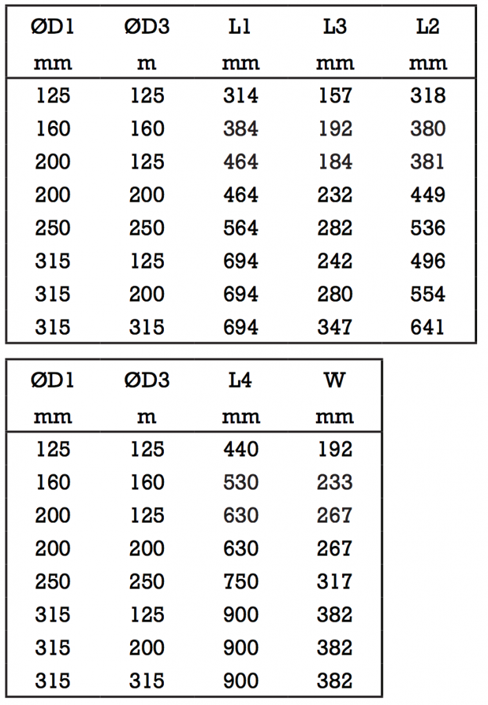 CR T-pieces are made of compressed glass wool with inner & outer surfaces covered by a layer of CR Foil.
Average insulation thickness ≈ 30mm.
The standard circular nipple fits inside the neck of the CR T-piece.
Water vapor resistance > 140m2 h Pa/mg
CR Nipple
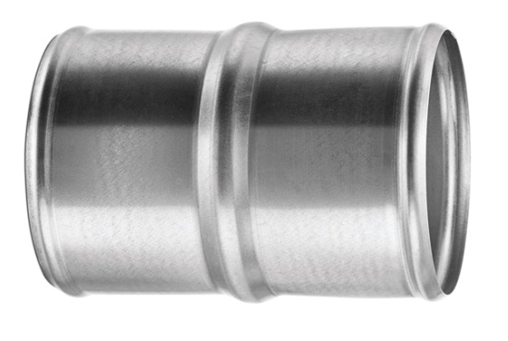
CR Sleeves cover the ends of CR Ducts when joints are created.
Made of polyurethane mixture, including flame retardant.
CR Adapter
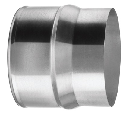
CR Adapters connect products with standard circular nipple dimensions to the corresponding CR Duct sizes.
Made of galvanized sheet metal.
Sleeve
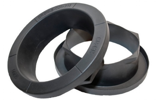
CR Sleeves cover the ends of CR Ducts when joints are created.
Made of polyurethane mixture, including flame retardant.
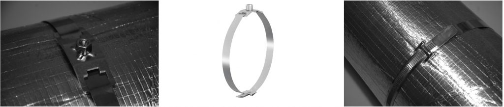
Clamp
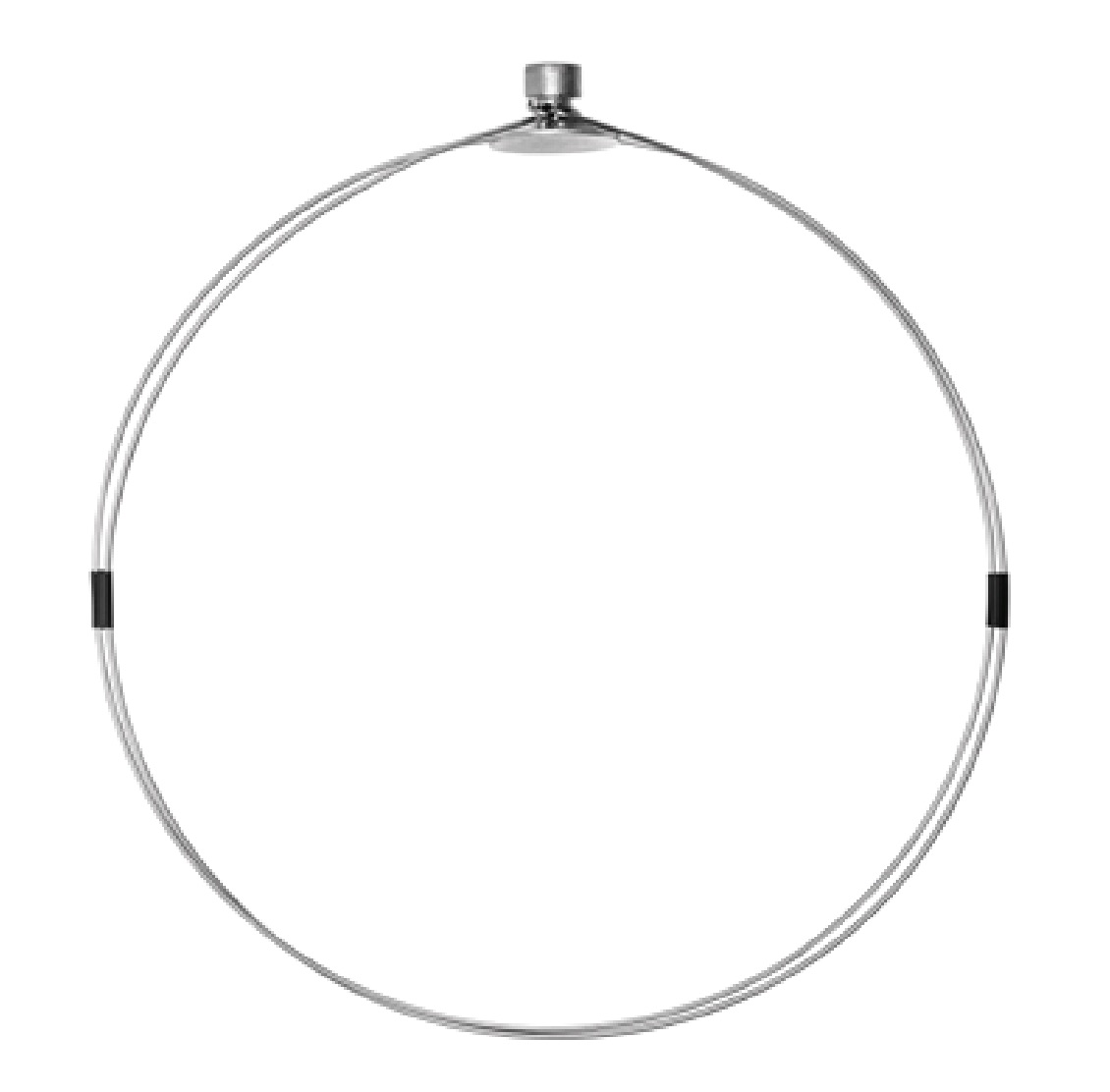
CR Clamps tighten CR Ducts around joints created.
Made of stainless steel.
Utilize hex bit, size 8.
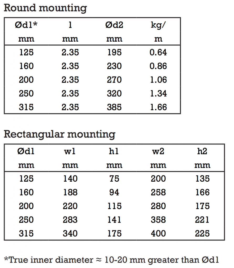
Transformer
![]()
CR Transformers are placed around CR Ducts when installations require rectangular dimensions.
Made of .7mm plate steel, coated with aluzinc.
Tape
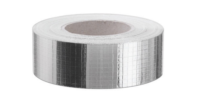 CR Tape is non-reversible.
Made of aluminium foil with tightening glue.
Width: 50mm 100mm
Proper Hanging
Attachment to the structure
This should be done in accordance with building specifications per standard EN 12236 protocols. When mounting the CR Duct System to the fixed building structure, M8 steel threaded rod should be used. CR-CM8 has a click function that allow attachment by directly pressing M8 rods into the fixture. CRM8 must be screwed onto the fixture.
Hanging support
CR Straps should be drawn through the openings of CR-CM8 or CRM8 fixtures. The flat end of the strap is then wrapped around the exterior of the CR Duct, then through the fixed end and secured by the ridged bindings. Leaving a loose binding before hanging will allow easier adjustments made to the placement of M8 fixtures along the duct surface.
Hanger spacing
Hanging support of the CR Duct System should be maintained at a minimum of every 2.3 meters of duct length and within 10 cm of any joint. If CR products are installed vertically, the support must be placed a minimum of 50 cm from joint connections, with further support spaced at a minimum of every 2.5 meters. When combining the CR Duct System with sheet metal ductwork, support should be placed within 10 cm of joints and every 2 meters.